Placa ESP32
Pinout placa ESP32
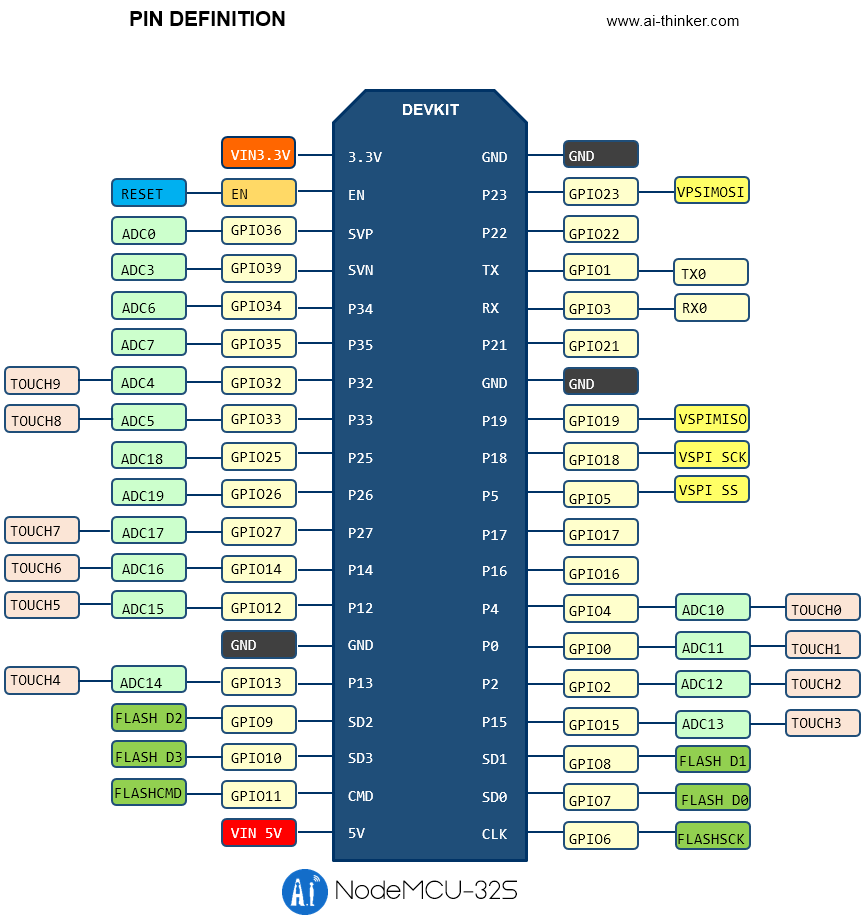
A continuación se muestra el diagrama de pines de la placa NodeMCU ESP32 (del fabricante ia-thinker) que es la placa disponible en el laboratorio:

La siguiente tabla tomada del datasheet, describe cada uno de estos pines
1
3.3V
Module power supply pin
2
EN
Chip Enabled Pin, Active High
3
SVP
GPIO36,ADC1_CH0,RTC_GPIO0
4
SVN
GPIO39,ADC1_CH3,RTC_GPIO3
5
P34
GPIO34,ADC1_CH6,RTC_GPIO4
6
P35
GPIO35,ADC1_CH7,RTC_GPIO5
7
P32
GPIO32, XTAL_32K_P (32.768kHz Crystal input), ADC1_CH4, TOUCH9,RTC_GPIO9
8
P33
GPIO33, XTAL_32K_N (32.768kHz Crystal output),ADC1_CH5, TOUCH8,RTC_GPIO8
9
P25
GPIO25,DAC_1,ADC2_CH8,RTC_GPIO6,EMAC_RXD0
10
P26
GPIO26,DAC_2,ADC2_CH9,RTC_GPIO7,EMAC_RX_DV
11
P27
GPIO27,ADC2_CH7,TOUCH7,RTC_GPIO17,EMAC_RX_DV
12
P14
GPIO14, ADC2_CH6, TOUCH6, RTC_GPIO16, MTMS, HSPICLK, HS2_CLK,SD_CLK, EMAC_TXD2
13
P12
GPIO12, ADC2_CH5, TOUCH5, RTC_GPIO15, MTDI, HSPIQ, HS2_DATA2,SD_DATA2, EMAC_TXD3
14
GND
GND
15
P13
GPIO13, ADC2_CH4, TOUCH4, RTC_GPIO14, MTCK, HSPID, HS2_DATA3,SD_DATA3, EMAC_RX_ER
16
SD2
GPIO9, SD_DATA2, SPIHD, HS1_DATA2, U1RXD
17
SD3
GPIO10, SD_DATA3, SPIWP, HS1_DATA3, U1TXD
18
CMD
GPIO11, SD_CMD, SPICS0, HS1_CMD, U1RTS
19
5V
Module power supply pin
20
CLK
GPIO6, SD_CLK, SPICLK, HS1_CLK, U1CTS
21
SD0
GPIO7, SD_DATA0, SPIQ, HS1_DATA0, U2RTS
22
SD1
GPIO8, SD_DATA1, SPID, HS1_DATA1, U2CTS
23
P15
GPIO15, ADC2_CH3, TOUCH3, MTDO, HSPICS0, RTC_GPIO13, HS2_CMD,SD_CMD, EMAC_RXD3
24
P2
GPIO2, ADC2_CH2, TOUCH2, RTC_GPIO12, HSPIWP, HS2_DATA0,SD_DATA0
25
P0
GPIO0, ADC2_CH1, TOUCH1, CLK_OUT1,RTC_GPIO11, EMAC_TX_CLK; Download mode: external pull low, running mode: floating or external pull high
26
P4
GPIO4, ADC2_CH0, TOUCH0, RTC_GPIO10, HSPIHD, HS2_DATA1,SD_DATA1, EMAC_TX_ER
27
P16
GPIO16, HS1_DATA4, U2RXD, EMAC_CLK_OUT
28
P17
GPIO17, HS1_DATA5, U2TXD, EMAC_CLK_OUT_180
29
P5
GPIO5, VSPICS0, HS1_DATA6, EMAC_RX_CLK
30
P18
GPIO18, VSPICLK, HS1_DATA7
31
P19
GPIO19, VSPIQ, U0CTS, EMAC_TXD0
32
GND
GND
33
P21
GPIO21, VSPIHD, EMAC_TX_EN
34
RX
GPIO3, U0RXD, CLK_OUT2
35
TX
GPIO1, U0TXD, CLK_OUT3, EMAC_RXD2
36
P22
GPIO22, VSPIWP, U0RTS, EMAC_TXD1
37
P23
GPIO23, VSPID, HS1_STROBE
38
GND
GND
La siguiente tabla muestra de manera resumida los diferentes pines agrupados por funciones:
Digital (Only input)
P34, P35, SVP, SVN
Analog in
SVP, SVN, P35, P34, P32, P33, P25, P26, P27, P14, P12, P13, P15, P2, P0, P4
PWM
SVP, SVN, P35, P34, P32, P33, P25, P26, P27, P14, P12, P13, P15, P2, P0, P4
Serial (UART)
Tx, Rx, D8, D7
I2C
P22, P21
Digital SPI
P23, P19, P18, P5
Flash SPI
CLK, SD0, SD1, CMD, SD2, SD3
Capacitive touch
P0, P4, P2, P15, P13, P12, P14, P27
Para conocer mas sobre el uso de los pines para esta plataforma se recomienda ver la pagina: ESP32 Pinout Reference: Which GPIO pins should you use?
Arduino core for the ESP32, ESP32-S2, ESP32-S3 and ESP32-C3
De manera similar al ESP8266, el ESP32 puede programarse usando el API arduino. Para mas información puede consultar la documentación de este Core en el siguiente link.
Antes de empezar a usar el core para el esp32s, es necesario instalar las librerias necesarias para ello. Para esto siga las instrucciones que se describen en el link Installing the ESP32 Board in Arduino IDE (Windows, Mac OS X, Linux)
Antes de analizar los ejemplos que se muestran a continuación se recomuenda que de un vistazo al link Getting Started with the ESP32 Development Board
Ejemplos
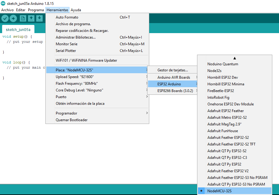
Antes de empezar a realizar los ejemplos, se debe seleccionar la tarjeta con la cual se va a trabajar (NodeMCU-32s) tal y como se muestra en la siguiente figura para el IDE de Arduino:

Tenga en cuenta que antes de empezar la descarga del programa debe presionar el botón boot de la placa del ESP32 y liberarlo cuando salga el mensaje “Connecting…” en el IDE de Arduino. (Para más información ver la sección Troubleshooting en el siguiente link)

Ejemplos
Ejemplo 1
Poner parpadear un led a un periodo de 2 segundos usando el led de la tarjeta ESP32 (Ejemplo adaptado de: Blink).
Componentes
1
U1
1
Tarjeta de desarrollo ESP32
Esquematico

Conexión

Archivo Fritzing
Código
Simulación
El montaje asociado a la simulación se muestra a continuación:

Ejemplo 2
Prender el led integrado de la placa ESP32 cuando se presiona un switch. (Código adaptado para el ESP32 del link How to Wire and Program a Button)
Componentes
1
U1
1
Tarjeta de desarrollo ESP32
2
SW1
1
KY-004 BUTTON (37 Sensor Kit)
Esquematico

Conexión

Archivo fritzing
Código
Simulación
A continuación se muestra el montaje de la simulación:

Para entender mas se recomienda que mire el tutorial ESP32 Digital Inputs and Digital Outputs (Arduino IDE).
Ejemplo 3
Modifica el brillo de un led (conectado al pin GPIO2) de manera automatica. (Código adaptado para el ESP32 del link Fading a LED)
Componentes
1
U1
1
Tarjeta de desarrollo ESP32
2
SW1
1
KY-004 BUTTON (37 Sensor Kit)
Esquemático

Conexión

Archivo Fritizing
Código
Simulación
A continuación se muestra el montaje de la simulación:

Ejemplo 4
Llevar al puerto serial el valor de voltaje de un potenciometro leido a traves del puerto analogo. Adicionalmente empleando una señal PWM, variar el grado de luminosidad del led integrado en la tarjeta ESP32.
Componentes
1
U1
1
Tarjeta de desarrollo ESP32
2
SW1
1
KY-004 BUTTON (37 Sensor Kit)
Esquemático

Conexión

Archivo Fritzing
Código
Simulación
A continuación se muestra el montaje de la simulación:

Para comprender mejor este ejemplo se recomienda reforzar viendo el link ESP32 ADC – Read Analog Values with Arduino IDE.
Referencias
Last updated